Finally I got around to figuring this out. Had to poke around a little bit.
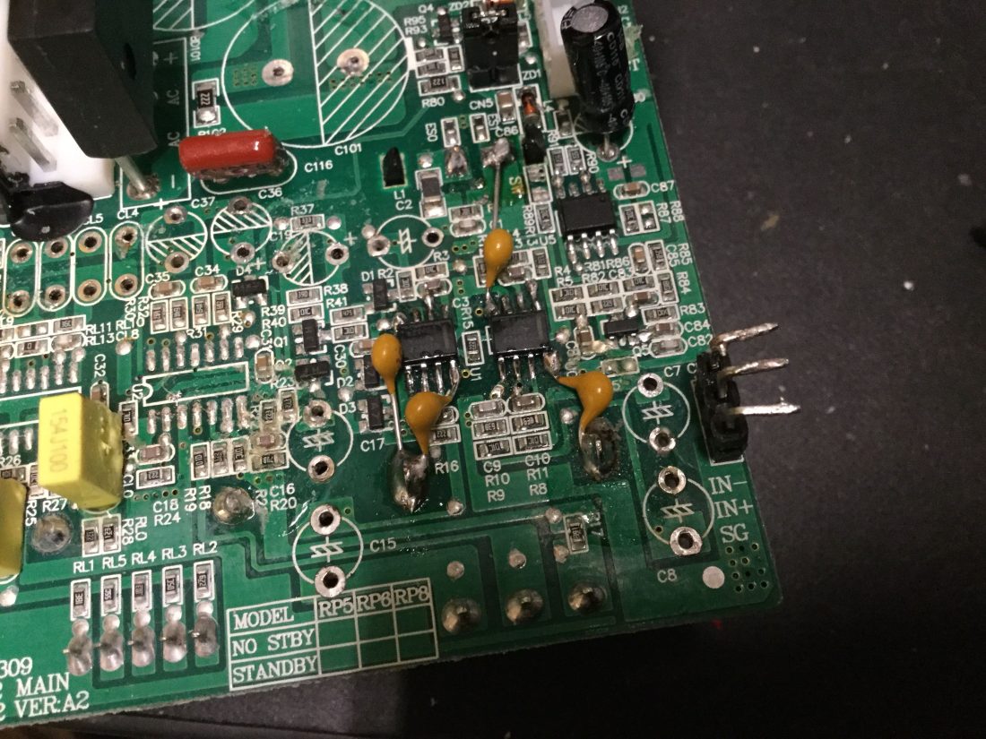
Ran across this schematic in the land of diy forums. It’s for the G2 Rokit 6 amps, which had the notorious black goo of death problem, so totally different design (well, probably not that different… these budget companies never really redesign their stuff if they don’t have to, unless they can make it simpler/stupider), but it struck me that their limiter was using just one bipolar transistor right after the input buffer, so I went looking for lone transistors near the input, and lo and behold, there is only one (Q5, just above the right-most large ceramic capacitor).
Oscilloscope revealed bits of signal being leached off, so it seemed I had found the culprit. Removed Q5, but both amplifiers suddenly muted… hm.
Traced signal from top-most pin of Q5, found it running to the ‘mystery chip’ just above, U5. Looks like it’s some kind of gate circuit: when it receives enough input voltage at pin 5 (lower left pin), seems like it opens pin 4 (upper left) and passes 5V, which is what the amp circuits need to unmute and shut off standby (datasheet for TDA7296 actually specifies 3.5V minimum to disengage mute/standby function).
This reveals a couple of things about KRK’s design. First off, the limiter is running all the time. Even at relatively low levels it seems to be leaching signal, and globally for both treble and bass. Secondly, the mute circuit depends on the output of the limiter in order to engage, so the limiter needs to be operating rather aggressively in order to unmute the amplifiers. This is why, when I removed Q5, the mute circuit wasn’t seeing any input. I’ll say again: IF YOU HEAR ANY SOUND, THE LIMITER IS LIMITING, A LOT. 🤦♂️
So… remove the transistor (hot air is easiest), remove the IC, and short pins 3 and 4 as shown (I used a little piece of wire clipping).

Now the amp engages immediately, without any lag. There are electrolytic caps decoupling the input to the mute/standby pins in the amplifier, so there won’t be a big pop. Can see the voltage at pins 9/10 of TDA7296 rising and falling gently with on/off.
Things sound ‘snappier’, more precise––these are some real speakers now! This project has officially reached it’s zenith. EDIT: I’m shitting my pants at how amazing this sounds. All my previous mods really seem to have come to life now, the low end is incredibly clear and integrated (it’s like all the overtones just lock), I find I’m listening with the volume a bit lower, and both speakers sound more balanced (the right speaker always felt just a little softer, and they’re ‘matched’). My reference recordings sound uncanny. And just over a little transistor…
*PROCEED AT YER OWN RISK* I listen primarily to Classical stuff, I’m not pounding EDM or anything. I assume this circuit is here for a reason.
If you want someone to do this for you, check out this guy: https://www.danieldialatone.com/gallery. Used to be a head engineer for Black Lion Audio, studio monitor ‘enhancements’ are his specialty. I just use the TI SoundPlus series of opamps (which I think sound great, enough of an improvement), based on their functional equivalency to what’s on the board (FET/bipolar, comparing input impedance, etc) he actually hand selects different opamps for their unique flavor. If my amateurish experimentation got me this far, just think what a real pro can do!
Coming up: RME UFX mods, Presonus DP88 mods, Behringer ADA8200 (re-)mods, Yamaha TG77 mods

Legendary work just got rid of the auto standby on my set thanks to you.
Was driving me mad not been able to listen to things quietly without em turning off.
LikeLike
Glad it helped! Just be sure to shut them off periodically. The heat sinks do get hot when the amplifiers are always on, and I actually just had one of mine go into thermal shut down (160˚C!) the other day while I was using them as monitors in a slightly-warmer-than-comfortable theater.
But I am really, really glad that when I switch them on, they’re ready to go… Cheers!
LikeLike
Hi! I just found your great mod and tried it. But I have no sound at all. The monitor switches on but no sound at all. I am talking about a Rokit 4 g3. But it has the same pcb and same components.
I took of both, transistor and ic and shortened pin 3-4.
Is there anything else you modified maybe?
Thanks a lot in advance!
LikeLike
Ugh, bummer, I’m sorry to hear that… modding is always a fickle thing. I’ve often created a few mysteries for myself, which were later revealed to be small oversights.
Basically what needs to happen is pin 9 of the TDAxxxx amplifier chips (same for HF and LF? I can’t remember…) needs ~5VDC to prevent standby. The unmarked chip I say to remove is a gate of some kind, and I think I traced one of those pins (3 or 4, I can’t remember) to the circuitry feeding pin 9. If you have a multimeter, see if you can probe pin 9 on the amplifier chip to see if it’s getting 5 volts, then work your way back. In any case, you don’t *need* 5 volts from those pins, you can get it from someplace else, but you might need to poke around.
Be careful! There’s a lot of voltage on that board…
Just FYI, see p.2 and bottom of p.3: https://www.st.com/resource/en/datasheet/tda7294.pdf
LikeLike
Ok, understand. Here it is a TDA 7265. So the corresponding pin would be “mute”, pin 5?
Click to access tda7265-957142.pdf
Cheers, man. I just saw you’ve been in Berlin, recently!?
Thx a lot!
LikeLike
So I somehow succeeded. I took the 5V from the jumper beside the relais – connector and connected it to pin 5 of the TDA.
But the strange thing is sometimes it is switching the amp on and sometimes it won’t.
If yes, everything is fine and it works and stays on.
If it does not then it’s just dead, no sound, although the rest is on.
I must admit that I am not good in electronics although I am good in soldering…
ok now I outed myself.
Best from Berlin
LikeLike
wow, sorry about the rabbit hole here. is it working now? maybe a stray bit of solder causing a short somewhere? is it the same problem in both speakers?
LikeLike
I think it has to do with the 5V. Switching on and of 2, 3 times activates it. Maybe the 5V is not stable enough?
So far I only started with one speaker. I’m gonna use them for Talkback- Monitor, which is maybe a dumb idea… 😂
But what I can say right away is, if it’s working the monitor sound much more open and dynamically more precise.
I will try out a different 5V source tomorrow.
Btw: what part of the circuit opens the preamp- audio path? Could it be that this is the problem? On pin 1 of the IC I have 5 V… wa s it the same in your monitor? Maybe the short should be somewhere else?
LikeLike
Yeah, actually, now that you mention it, I don’t think there’s any kind of regulator for 5V, seems to be achieved with voltage divider. I have been planning to dig into my pair again to change a couple capacitor sizes and add some extra film bypass caps I overlooked, so I’ll revisit the limiter/mute function again.
Today I finished up a mod on a Presonus HP amp, and one of the channels simply refused to work. There was the *tiniest* solder bridge shorting one of the inputs to ground, I couldn’t see it, but I reworked a bunch of pins and, voila, it works. They don’t call it a voided warranty for nothing…
LikeLike
hello, I have two RP5 G3 and I also want to remove this standby mode. I just read your answer for the 5V for the person with the RP4 … I just have to remove the IC and the transistor and remove the small connections to the legs 3 and 4? it will be ok by doing that you think? (or I must do something for the 5V) … thank you for your blog I think it help lots of people. I heard the RP5 G4 demo on Youtube for a solution but really
dont like the sound of them, I love the sound of the RP5 for work in my home studio.
LikeLike
Not remove connections to 3+4, but short them. The effect of this solution is that you supply the standby/mute pins on the TDA chip with 5 volts, which appears to be connected to one of those pins (can’t remember which one). Use a multimeter to check continuity, just in case.
Just a word of caution, this is removing the limiter as well, which means the voice coils are more susceptible to damage from sharp transients or sustained thumping. Just know you’re taking that risk and go easy on the volume.
LikeLike
Ryan, there is a circuit somewhere on that board, that monitors for audio input, and activates the standby after 30 minutes of inactivity. It should be possible to find that timer and deactivate it, which would keep the limiter active, for those of us who don’t want to have to worry about frying our speakers. I hate these speakers, and would get rid of them if I could afford to. Please figure out how to deactivate that thirty minute timer circuit. I’m beggin’, man…
LikeLike
Yes, it’s actually on the amplifier chip itself. If you look at the datasheet for the amplifier chips, there are two pins, “mute” and “standby”. You just need to provide them with at least 3.5VDC in order for the circuit to stay open. I know there’s 5VDC on that board, you could run a small jumper. You can access those pins from underneath the PCB.
LikeLike
Thanks for the reply. I did see that on the datasheet, but from what I’ve read, those pins are controlled by the system in a specific way, to avoid loud pops and clicks at powerup, etc. I’ve read your article on removing the limiter circuitry, but I don’t want to do that either – I don’t have the proper equipment.
It appears that U1, U5, and Q5 form some sort of timer circuit that controls standby. I was hoping that there was a way to deactivate the timer part, without causing the loud pops that might come from just tying pins 9 and 10 open on the output chips to Vc. Again, thank you for taking the time to reply. I think I’m just going to have to admit defeat.
P. S. I did once get instructions from Gibson on how to defeat that circuit. I accidentally let the email permanently delete itself, and now, Gibson refuses to send me the instructions again. If I recall correctly, the trick was to jumper U1, pins 1 and 5 together. But, I’m not going to try it. I can’t afford to be wrong, and fry my speakers. I wish I could afford to sell them and replace them, but I can’t right now.
If you ever figure this out, please post instructions on your website…
LikeLike
I do believe there’s a capacitor tied to those pins which is included specifically to prevent sudden pops. I write about that in the post:
“Now the amp engages immediately, without any lag. There are electrolytic caps decoupling the input to the mute/standby pins in the amplifier, so there won’t be a big pop. Can see the voltage at pins 9/10 of TDA7296 rising and falling gently with on/off.”
LikeLiked by 1 person
Again, I should reiterate that these speakers are built to a price point, and so all these “features” double as protections for a scantily-clad design. Proceed at your own risk, as always. However, the worst that happens is you cook the voice coils and have to replace either the tweeter or woofer (ca. $20/$50, respectively), but even then the amplifier chips themselves have an internal thermal shutdown circuit, so you’d really have to be hitting them hard and continuously to do any real damage.
LikeLike
Oh yes, I recall reading that – I’ve read the article several times, looking for clues. Obviously, the modification would have to be done on both amplifier chips, but I’m wondering if it would need to be done on both pins 9 and 10 of each IC, or just the Standby pin – pin 9. Also, the data sheet shows resistors being used between the pins and Vdc. I’m assuming that would be a wise idea as well.
LikeLike
Regarding your caution, I do understand the risk. That’s why I don’t want to remove the IC and bypass the limiter – just eliminate the auto-standby.
LikeLike
There should be an easy way to bypass the auto-standby without removing the limiter – a jumper or resistor… Could you PLEASE figure that out, and let us know how to do that?
LikeLike
Perfect. One of my speakers had random dropouts of the audio. Thought it was because of bad soldering and could not find the dad spot. Your post gave me the hint where to look. Removed the transistor and the IC and shorted two Pins. 3+4 did not work. I had use 1+4 because there was no 5V on Pin 3. It’s working perfect now. Sound is better and I can use the speakers on low signal now without them turning of. This was really annoying. Thanks a lot for the good work. Greetings from Switzerland! Roman
LikeLike
Finally get rid of the auto standby for good.
Check out the instructions in the thread here:
https://www.eevblog.com/forum/beginners/mixing-lead-solder-with-lead-free-solder/
I performed the mod to my two KRK Rokit 8 G3’s, and they no longer go into standby.
It would be trivial to add a switch to enable/disable auto standby if you still wished to have that feature at times.
As with any mods, perform them at your own risk. A speaker that goes into auto-standby is still better than a speaker that stops working because your electronics ran out of smoke.
LikeLike
Il est impossible de contourner la mise en veille automatique sans retirer le limiteur car tout se passe dans la puce inconnue.
Si on enlève cette puce, il faut aussi shunter les pines 1 et 2 de façon à ce que le relais soit activé par la sortie “ST”, sinon l’alimentation est coupée par le relais.
Après avoir supprimé U5, comme décrit par minimaliste, on peut toujours par la suite protéger les amplis par un petit montage limiteur en récupérant le signal à la broche 5 de U5 pour entrer sur un comparateur après avoir redressé le signal comme pour un vu-mètre. La sortie de ce montage sera reliée à la pine 4 de U5 sans mettre de shunte sur les pines 4 et 3. Il faut tout de même avoir de bonnes notions en électronique pour effectuer ce type de modification. Je vais essayer de faire ce travail pour les KRK Rokit 5 G3 de mon frère.
J’espère que mon idée pourra aider certains !
Cordialement.
LikeLike
Looking to have this mod done for my (new) pair of RP5’s. I have zero solder experience. The link for Danieldoesmods is not working. Know of anyone else? Thanks for the info. Great blog!
LikeLike